Tone Pot as a Low Pass Filter
A reader recently asked me a question about the low pass filter in a guitar tone circuit:
Will a 250k tone pot with a .02uF capacitor sound the same as a 500k pot with a .01uF capacitor (all else being equal)?
This is an interesting thought experiment, and the answer is simultaneously obvious and non-intuitive.

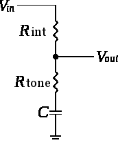
and the associated formula for cutoff frequency as 1/2piRC, and conclude that the two circuits would behave identically (since 250k*.02uF is the same as 500k*.01uF). However, the problem there is that the R in the formula is not the tone pot! That R is really the internal resistance of the guitar, or the resistance of the pickup.

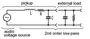
How’s that for insanely non-intuitive?! Bill points out that the lower square root term only works with tone resistances less than about 20k (since otherwise the value would go negative producing imaginary numbers in the square root), thus explaining the often limited useful range of tone pots, and why log taper pots are more useful for tone than linear. Nevertheless, this seems to be an over-idealized formula, since in practice, I do see more variation in the tone pot even at higher resistances. This formula doesn’t seem to capture the full complexity of the reactive network made up of pickup inductor, and overall circuit resistance and capacitance (including cable capacitance).
Ok, so math is clearly the wrong way to think about this!! Too complicated! Back to the original question. Let’s think of it more simply. Imagine you turn both pots down to zero- you’re basically eliminating the variable resistance pot and wiring the cap directly to ground. Of course, the larger capacitance .02uF will sound darker than the .01uF. So they’re obviously not equivalent circuits.
Next up, experiment! Grab a couple pots, caps and some alligator leads and try it out! You’ll find that they do indeed sound quite different. The larger capacitance with the smaller pot resistance sounds darker, no matter how you slice it, when compared to the 500k pot and .01uF cap. Even with both pots up full, the larger capacitance with the smaller pot sounds a bit darker.
This all begs the question, why do guitar manufacturers often pair a 250k tone pot with a .047uF cap, versus the .022uF cap with 500k pots? The former will produce a darker sound both because of the larger capacitance but also because of the increased load on the pickup from the smaller resistance. “Double whammy” as Bill points out at the end of his paper.

The Overall Guitar Circuit - Planet Z
August 19, 2014 @ 6:29 am
[…] have written before about the tone circuit as a low pass filter, but to understand the bigger picture, it’s important to think about the overall guitar […]
February 18, 2018 @ 5:48 pm
So then what equation do you use if you want higher than ~20k?
February 18, 2018 @ 8:34 pm
My argument in this post was that these equations are too complicated to be useful (at least for me, lacking a higher math degree!) In any case, Bill accepted the limitation in his model of the guitar circuit, since even a perfectly ideal human ear can only hear up to about 20k.
-John