Pickup DC Resistance and Output Levels
Here’s another excellent article on guitar pickups, courtesy of Pete Biltoft at Vintage Vibe Guitars. Thanks Pete for the permission to post this here!
August 2011
DC resistance measurements are widely used as a gauge of the “output” of passive magnetic pickups. This use of DC resistance is both technically incorrect and often misleading; to find out why, read on…
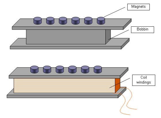
In its most basic form a single coil magnetic pickup consists of a permanent magnet or set of magnets typically housed in an electrically insulating coil form (commonly referred to as a bobbin) and a coil of electrically insulated wire wound onto the bobbin (see Figure 1).
Figure 1. Simplified drawing of an unwound and a wound single coil pickup bobbin.
In operation, the vibrating strings of the instrument (which contain iron and nickel, both magnetic materials) cause the magnetic field of the pickup magnet(s) to fluctuate.
This fluctuating magnetic induces free electrons in the coil windings to oscillate creating an alternating current (AC) signal which is the output of the pickup. Note that the pickup’s output is most often a complex AC waveform which may be characterized by its voltage and frequencies as shown in Figure 2.
Figure 2. Simple and complex AC waveforms. In each plot the horizontal X-axis represents time [seconds] and the vertical, Y-axis represents voltage [volts].
Important fact #1: the output of a pickup is its peak to peak (+V and –V) voltage; the DC resistance of a pickup is not a measure of output.
Important Fact #2: The output of a passive magnetic pickup is predominantly a function of the number of turns on the coil, the geometry of the coil and the magnetic field strength of the magnets in the pickup.
In order to achieve the proper amount of gain, many turns of coil wire are wrapped on the bobbin; this number can range from 2,000 to over 10,000 in passive magnetic pickups. As a side note, active pickups which use a battery powered pre-amplifier to boost the signal can have fewer turns of coil wire. Within limits the output of a passive magnetic pickup increases with the number of turns on the bobbin.
The wire used in most modern guitar pickups is a small diameter electrically insulated copper wire ranging in wire size from 38 gauge [38 AWG (American Wire Gauge)] to 46 gauge [46 AWG] with the most commonly used sizes being 42 AWG and 43 AWG.
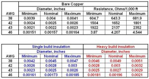
Coil wire used in pickups has an electrically insulating coating which prevents neighboring coil windings from creating a short circuit. The materials used to form this insulating coating have varied over the years and includes: enamel, Formvar, polyester and blends of other electrically insulating materials. In addition to the composition of the electrically insulating coating, the coating thickness plays a critical role in both the physical size of a wound coil and the tone of a completed pickup. Coating thicknesses are typically described as “Single Build” and “Heavy Build”. Data for the diameter of bare copper wire, wire with Single Build and Heavy Build and the resistance per 1,000 foot of length is presented in Table 1.
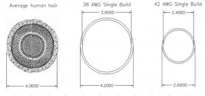
For reference, the mean diameter of human hair is approximately 0.004 inches.
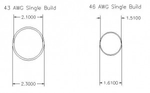
Figure 3. Scale drawing of cross sections of human hair and coil wires drawn to a scale of 1,000:1. In each drawing of coil wire cross sections both the diameter of the copper core and the diameter of the core plus the single build insulation is indicated.
Table 1: Data for copper wire sizes commonly used in magnetic pickups.
Note that for samples of 1,000 feet of 42 and 43 gauge wire the DC resistances are 1.5 k-Ohm and 1.9 k-Ohm respectively.
A standard strat size neck position single coil pickup is often wound with 7,500 turns of 42 gauge wire with a resulting DC resistance of approximately 5.5 k-Ohm. From this DC resistance we can calculate that the length of the coil windings on this pickup is approximately 3,657 feet [almost 7/10ths of a mile!].
Winding an identical strat style pickup bobbin with 7,500 turns of 43 AWG wire would result in a DC resistance of approximately 7 k-Ohms. This DC resistance reading is 27% higher than the reading for the strat pickup wound with 42 gauge wire and yet the true output of these two pickups as measured in volts would be very similar.
Important fact #3: When comparing two similar pickups, using only the DC resistance measurement of the pickups may be a misleading indicator of the performance of a pickup.
Other factors which influence the DC resistance readings for pickups include the bobbin size and the degree of scatter-winding. As the length and width of a pickup bobbin increases the length of coil wire per turn on the bobbin increases. Charlie Christian style single coil pickups, for example tend to have a larger bobbin middle section where the coil windings are placed than tele neck position single coil pickups. As a result, a CC style pickup wound with the same number of turns of the same gauge wire as a tele neck position pickup would have a higher DC resistance. As a coil is wound on a bobbin the new coil windings are laid over the earlier windings and the bobbin size effectively increases such that a turn at the end of a coil can be up to 20% longer than the first turns on the bobbin.
Scatter winding is a term widely used to describe the “rastering” or side to side motion used in the process of winding coil wire onto a bobbin. Scatter winding can be slow, in which case the location of a turn of coil wire on a bobbin is close to that of its immediate predecessor and all of the windings are roughly parallel to each other. Fast scatter winding results in coil windings which are laterally displaced relative to the preceding coil windings and may be laid down at angles relative to each other. The DC resistance of a fast scatter wound coil can be significantly higher than that of a similar slow wound coil and yet the output of these two coils would be virtually identical.
In summary, DC resistance measurements of passive magnetic pickups, while relatively easy to make are often not a good gauge of the performance of pickups. To make a more complete comparison of pickups one should know the wire gauge used in the coil of each pickup, the number of turns on the coils and something about the strength of the magnets in the pickups.
I hope this information is helpful to you.
Best wishes,
Pete Biltoft
Vintage Vibe Guitars
website: www.vintagevibeguitars.com
email: [email protected]


February 10, 2012 @ 8:46 am
Great article on explaining DC resistance, and output levels. It amazes me how so many guitarists hang their hats on nothing more than DC resistance to explain their pickups. There is so much more going on than that.
February 10, 2012 @ 9:59 am
Definitely! Pete writes great articles.
Hey, I just visited your blog, and your guitar-build turned out great! I admire your effort- someday I hope to do a very similar project.
-John
November 28, 2012 @ 3:11 pm
I agree.
September 26, 2012 @ 5:40 am
Does the gauge of the wires going from the pickups to the pots etc. matter when the gauge of the wire around the coils is so thin? I wanted to get a shielded 2-conductor wire from my Telecaster neck pickup to the electronics cavity, for a 4-way switch mod. The only thing I could find is 28 awg. I’d thought that would be a bit to thin for audio, but maybe it doesn’t matter for such a short length?
September 27, 2012 @ 9:55 am
The resistance of the wire is a function of both its gauge and its length. You’ve got nearly a mile of wire around your pickup coil, so it needs to be thin. Don’t forget thinner wire has
lessMORE resistance than heavier gauge wire.In any case, there’s only a few inches between your pots, jack, etc, so it’s much less significant.
The thin-gauge center wire in shielded cable is totally normal. This is wire from stewmac is pretty standard, with 26 gauge center wire: http://www.stewmac.com/shop/Electronics,_pickups/Supplies:_Wire,_cables/Shielded_Guitar_Circuit_Wire.html
John
September 27, 2012 @ 4:33 pm
Thanks for your help. I probably didn’t explain this properly. What I meant is I wanted to have a wire with 2 conductors PLUS shield to go from my neck pickup to the controls cavity. I suppose the 28-awg I found will do, then. I have already ordered and received it in my mail box.
April 18, 2018 @ 11:10 am
I’m sorry to be the signal integrity police, but finer wire has more resistance than thicker wire. You can see that in the tables of the original article. Perhaps the gauge is the confusion? 42 is much thinner than 32, and therefore is more resistive.
Secondly, resistance is always DC resistance. Impedance is always AC resistance. Scattered winding a wire OF THE SAME LENGTH cannot affect DC resistance, but it can affect AC impedance. If you measured a difference in DC resistance, is is because angling the wire as you wind it uses more wire than if you make neat slow raster windings. Plus, angling means you wind around a bunch of previous windings in one turn, rather than just following in between two previous windings underneath, so more wire used up for the same number of turns.
In other words, it’s not the turns that incur resistance, it is the total wire length. As for impedance, that is much deeper topic. But in short, no pun intended, a capacitor looks like a variable resistor to signals of varying frequencies. That causes non-linear response across the entire spectrum of notes or frequencies you can get out of a guitar. When you wind wire, you get capacitance between the windings. Why? Because in all electronics, C (capacitance) IS EVERYWHERE, because all it takes is two conductors close together, but insulated from each other. So pretty much any wiring has capacitance.
It also has inductance, which is the reciprocal of capacitance. Capacitors charge with voltage, but can discharge current, coils charge with current, and discharge with voltage — that’s why a rail gun needs a capacitor bank — for tons of current in a small time, but a Tesla coil puts out tons of voltage in a small time. Both are charged with a long time, so the power (Watts, or I*V) remains conserved. Therefore:
When you have a bunch of wire, you get resistance, which translates to impedance, however, impedance has a secondary “impedance” incurred by the reactance of the capacitance, dependent on frequency. That makes a voltage divider (two resistors). But, the division is dependent on the frequency — that is what you call a low-pass filter, which is why the highs roll off with passive pickups driving 20 foot cables. High output impedance means you cannot drive the capacitance of the cable (shielding near the inside conductor, but insulated = capacitance — same with twisted-pair).
And that, is why you use active pickups — has NOTHING TO DO with an amplifier. It’s not boosting the voltage or level of the signal. It is lowering the output impedance to a few Ohms, and it needs a battery to pump the current out through these couple of Ohms, instead of through 5k Ohms of coil. That current can only come from a switching device like a FET or other transistor, because that device has a low output impedance, whereas a mile-long piece of thin wire, is itself a device — with a very high output impedance — Proof: How do you limit current in a circuit? A resistor. So low output impedance is required to charge/discharge that cable’s capacitance as rapidly as possible, thus maintaining the original levels of even the high frequencies.
Nonetheless, thank you for writing one of the best article on the topic, compared to many others I’ve read. 2012….. Are we still alive?
— I was just looking for typical dBu levels from passive pickups — BTW, the proximity of the pickup poles to the string will greatly affect the output level, but will also magnetically dampen the string, meaning less sustain. I’m going to go beef up my calluses.
April 20, 2018 @ 10:13 am
Thanks for the comments. Note, the original article was written by Pete Biltoft. He’s still around at VintageVibeGuitars.com
June 17, 2018 @ 6:14 am
I am trying to understand how to increase impedance on pickups without changing the number of turns. If the coil is more uniform it will have a lower henrie value? So if I scatter the coil more in a guitar pickup, it will increase the impedance while keeping the coil the same number of turns? Thanks for your help.
October 10, 2012 @ 1:16 pm
I have to correct something: the thinner the wire, the HIGHER the resistance. (That’s why high-voltage, high-current power supplies use big bus bars, not hairlike wires.) There’s a mathematical formulation of it at
http://hyperphysics.phy-astr.gsu.edu/hbase/electric/resis.html
I agree that the couple of inches of wiring between pickup and pot, jack, etc. is not likely to make much difference unless you’re using something really bizarre, though.
October 10, 2012 @ 1:24 pm
Hi JD,
Thanks for correcting my dumb mistake! Not sure where my brain was that morning- not in my head apparently 🙂
John
August 5, 2014 @ 9:51 am
Hello I was wondering if anybody could tell me the factory resistance of a 1982 HAMER PROTOTYPE II humbucker. Im planning to get one re wound
and i have no idea what the ohms are supposed to be somewhere around 11 K i think but don’t know for sure
July 8, 2016 @ 6:35 pm
Great post, thank you! Cheers from Brazil
Pickup Inductance – Planet Z
June 28, 2017 @ 12:30 pm
[…] Here’s another excellent article on guitar pickups, courtesy of Pete Biltoft at Vintage Vibe Guitars. This makes a nice companion piece to Pete’s article on Pickup DC Resistance. […]
October 13, 2017 @ 7:28 pm
Hello guys, great informative article above! I have a project I’d like your thoughts on. I bought a set of cheap Chinese strat pickups that I want to rewind until the coil is just able to fit back in the cover, which is solid faced, fill the cover with epoxy, then replace the ceramic bar magnet with those 6mm dia neodymium magnets, one on the bottom of each pole piece, keeping in mind the polarities of course! Would this produce a good sounding pickup, or a piece of junk? What are your thoughts on a direction you might take to make a nice sound using the 3 things I mentioned – a lot of windings, epoxied coils, and neodymium mags? Thanks for your thoughts!
October 17, 2017 @ 8:01 am
Sounds like an interesting project! I’ve never tried building a pickup. Pete may be able to comment on specifics. I’m guessing that, as with any project like this, your most likely path to success and satisfaction is to plan on building several. Experiment and iterate on your design until you like it. Let us know how your project turns out!
-John