Building an iDevice Guitar Interface Cable
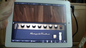
With the availability of apps like Amplitube, AmpKit, and Garage Band, it’s immediately obvious how this device can be an amazing guitar learning and practicing tool. I’ll talk more about that in another article. But before you can plug in your guitar, you need a special interface…
Before we talk about building our own device, let’s consider the alternative. There are a number of commercial interface products available. The less expensive ones plug in through the headphone/microphone jack like IK Multimedia Amplitube iRig, Peavey AmpKit Link, Griffin GuitarConnect. That’s the type of device we’ll be building. Then there are also the higher quality, more expensive products that have their own A/D converters and plug in using the dock connector- like Apogee Jam, Sonoma GuitarJack, Alesis iO Dock, Line 6 Mobile In and IK Multimedia iRig HD.
In part 1 of this 3-part video series, I introduce the project- how to make your own impedance matching, buffered guitar interface for the Apple iPad, iPod touch and iPhone. These iDevices all share a similar headphone/microphone jack specification, so this circuit should work with all of them.
I’ll show you why a simple unbuffered cable interconnect will sound terrible- because of the significant impedance mismatch between a passive guitar circuit and the iDevice mic jack. Also, the iDevice provides a 2.8V DC on the mic input to drive a microphone preamp, and as you’ll hear, this voltage totally screws up your guitar circuit.
This isn’t intended to be an ultra-high-fidelity interface. But trust me, it sounds good and costs very little. And the principals learned in this simple electronics project are the same as those required to make a guitar boost pedal like the Fulltone Fatboost.
In part 2 and part 3, I’ll explain all the electronics and show you how to assemble the interface.
Here’s some of the things you’ll need:
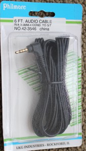
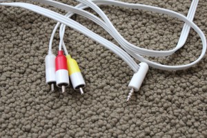
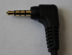
A 4 conductor cable, like these. Note the tip-ring-ring-sleeve connector:
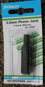
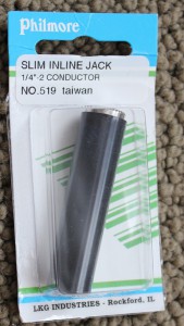
Also, a female 3.5mm phone jack for your headphones, and a 1/4” female jack for your guitar:
I’ll cover the electronics components in part 2.
September 23, 2011 @ 4:03 am
September 23, 2011 @ 7:47 am
September 23, 2011 @ 12:30 am
Fun because I know how it ends up…..
September 23, 2011 @ 2:55 pm
You definitely have the behind-the-scenes scoop.
Like – I shot most of this video in JUNE, and it took me this long to edit it all and tie up all the loose ends. I’m still shooting a couple of overdubs today for parts 2 and 3! I’m such an obsessive perfectionist. It’ll never be good enough- finally, I just have to cut the cord 🙂
-John
September 23, 2011 @ 7:46 am
September 23, 2011 @ 7:59 am
September 23, 2011 @ 9:24 am
Cant wait for 2 and 3, love your videos!
September 23, 2011 @ 12:39 pm
September 23, 2011 @ 9:12 pm
September 23, 2011 @ 1:06 pm
Simple JFET Preamp for an iDevice guitar interface - Planet Z
September 23, 2011 @ 5:59 pm
[…] up on Part 1, it’s time now to get into the heart of the […]
Assembling the iDevice Guitar Interface - Planet Z
September 24, 2011 @ 7:16 pm
[…] the exciting conclusion to the series, following up the intro in Part 1, and the electronics course in Part […]
November 7, 2011 @ 2:00 pm
November 23, 2011 @ 5:04 am
December 7, 2011 @ 10:58 am
A POD in your Pad - Planet Z
December 1, 2011 @ 8:02 pm
[…] interface connects to the 30-pin dock, which as I described in my DIY iOS interface project, is the higher-fidelity lower-noise way to get audio into your iPhone/iPad. This is because […]
February 21, 2018 @ 12:44 pm
Don’t know if it’s been addressed but how would one go about building an interface for an iPod touch lightning port?
February 21, 2018 @ 12:50 pm
That would be an entirely different and much more complicated undertaking, with D/A converters, etc. Take a look at this x-ray of Apple’s lightning-headphone adapter to get a sense of the complexity: https://ifixit.org/blog/8448/apple-audio-adapter-teardown/
-John
December 4, 2011 @ 2:05 pm
December 7, 2011 @ 10:59 am
December 20, 2011 @ 1:03 am
December 26, 2011 @ 10:19 am
January 4, 2012 @ 7:50 pm
January 4, 2012 @ 11:55 pm
January 15, 2012 @ 11:17 pm
Hello John, nice tutorial. Very simple. But i can ´t buy mpf102 transistor here. Please how do i select right transistor and resistor.
January 16, 2012 @ 12:55 pm
I listed some alternate parts in the schematic at the top of this post:
https://www.planetz.com/?p=1531
J201, 2n5457, 2n5458 will all work. You’ll need to change the source resistor a bit. You can scan through the comments in that post for suggested resistor values that people have tried.
Good luck!
John
January 20, 2012 @ 2:49 am
Hi, i used a BF245A transistor and i tried a lot of resistor. Finally i used 560Ohm source resistor. Hope be useful. Thanks a lot for guide
January 20, 2012 @ 9:23 am
Thanks for letting us know!
Happy to hear you got it working.
-John
March 3, 2012 @ 10:53 pm
Can I replace the MPF102 with a 2SC1815???
March 3, 2012 @ 11:01 pm
Also, Can this damage my Ipod at all?
March 4, 2012 @ 2:13 pm
Anything’s possible, but I’d guess it’s unlikely you’ll damage your ipod.
-John
March 4, 2012 @ 2:12 pm
For this project, better to use a JFET.
-John
March 9, 2012 @ 12:14 am
Hi, I want to build a pickup for my acoustic guitar and connect to my ipod then to my stereo. I was thinking using a piezo transducer, should I use this circuit as a preamp? Can you help me?
March 20, 2012 @ 10:26 am
I haven’t tried it, but I suspect it may work fine. It’s very simple to prototype and breadboard – try it and see how it goes!
-John
April 5, 2012 @ 5:24 am
Hi,
I did this last night. It DOES work, but not perfectly. I have this connected to a mid-2011 iMac. I’m only getting .7 volts DC between red lead and ground instead of the 2.8 VDC that this device wants to see. Is this a compatibility issue with the iMac vs the handheld devices?
Thanks,
Michael
April 5, 2012 @ 5:08 pm
I believe the iMac only has line in, no powered mic in. This was certainly the case when I tested on a 2011 Mac Book Pro.
So unfortunately, I don’t think you’ll have good success with this cable and the iMac.
John
July 31, 2012 @ 11:26 am
July 31, 2012 @ 11:32 am
July 31, 2012 @ 1:41 pm
another question do you know what is ettus research USRP n210 and what it does to an ios device?
July 31, 2012 @ 2:09 pm
Not something you’d use directly with an iOS device.
September 4, 2012 @ 11:51 am
October 1, 2012 @ 5:42 am
Hi have not found the 470 pf
can i replace with an other
thanks
December 27, 2012 @ 7:35 pm
Tried it using a headphone with built in mic. For some reason the two rings kept shorting out… tried everything I could think of. Will try again with better cable if I can find one…
January 14, 2013 @ 12:32 am
hi john… u are great… anyway i just asking bout using your schematic to garage band…. is it ok ? cause i never try it… i dont have garage band yet…
Thanks john
January 14, 2013 @ 12:06 pm
Yes, it works fine in garage band.
John
January 14, 2013 @ 12:43 am
another question john…. i have 3 option similar schematic, but i dont wich one better… cause im not a guitarist,
Another schematic:
http://sgitornado.altervista.org/diyirig.html
another schematic:
http://www.diystompboxes.com/smfforum/index.php?topic=85913.60
Big Thanks john
January 14, 2013 @ 12:09 pm
I obviously like the simplicity and size of my circuit. There’s nothing wrong with those schematics you linked – they just have more filtering, etc.
John
January 14, 2013 @ 12:09 pm
Built one using an enclosure to get the common ground I needed. Couldn’t find a 4 conductor cable with individual ground wires… I guess that would have been an 8 conductor cable. Problem I couldn’t out-think was how to get a ground to each of the split runs.
Also, have you tried this with an electric uke? I’m assuming it would be the same circuit?
http://www.amazon.com/Stagg-EUK-L-BK-Electric-Ukulele/dp/B005LD293C/ref=pd_sxp_grid_pt_1_0
January 18, 2013 @ 4:45 pm
My 4-conductor wire had a shield around each wire, available to be used as ground. They’re all electrically continuous to the plug shield. I demonstrate this is in my video starting at 3:10: http://www.youtube.com/watch?v=p1T8QmQowVQ#t=3m10s
If you’re asking if you can plug an electric Uke into an iDevice using this circuit, then I think it should work just like any other electric guitar.
-John
GarageBand feedback resolution - Planet Z
March 21, 2013 @ 8:47 am
[…] users of guitar interface cables like my DIY cable project have noticed an unreasonable amount of feedback when using Apple’s GarageBand iPad […]
Tonefreqhz DIY pedal. Update on build - Les Paul Forums
April 7, 2013 @ 2:02 pm
[…] audio codec sheild for arduino and maple | Open Music Labs Intro to DIY Pedal Building – Planet Z Building an iDevice Guitar Interface Cable – Planet Z I need to address the Resistor Values and also the reference ground voltage and also one of the […]
April 7, 2013 @ 10:18 pm
Hi John,
Thanks for all the great videos they have been very helpful to me and the links in your excellent blog are also priceless.
I am working on my own Pick up modelling pedal at the moment and this is as far as I have got.
http://www.youtube.com/watch?v=Trb3UAXWNn8
A couple of more weeks should get me somewhere near finished I think.
Thanks again
Roger
April 10, 2013 @ 4:17 pm
Hi Roger,
Interesting project! I’ve never worked with Arduino, but it’s been on my to-do list for some time. Such an inspiring platform.
-John
April 10, 2013 @ 10:45 pm
http://techwatch.keeward.com/geeks-and-nerds/arduino-vs-raspberry-pi-vs-cubieboard-vs-gooseberry-vs-apc-rock-vs-olinuxino-vs-hackberry-a10/
Hi John,
The Arduino is great and a fantastic learning tool. The creators of Raspberry Pi introduced it to get people back into programming as it was back in my School days ( Late 70’s)it was the PI that turned me on to Arduino and together they become the dynamic duo and peace will return to Gothem City.
In seriousness the Arduino, Pi, Beagle, Micro controller Community has really energised my own studies and the direction of my own creativity, coupled with Pure Data and also the Linux Audio project the vista of opportunities is both broad daunting yet very beautiful.
Its an exhilarating learning curve and your videos communicate the satisfaction and self affirmation that can be gleaned with some effort and not a little time. The results when applied to ones other hobbies though, are hugely rewarding.
In the initial link a new board called the Cubino is referenced and compared to the choices available in developer board world. I do like the look of that for my planned Rakarrack pedal which I am dubbing the ´´Daw on the floor´´. For now I am almost ready to assemble the final PD pickup replacer USB pedal controller, The Arduino whilst it can reference arrays is not in possesion of the horsepower required for real tine convolution Running Rakarracks convolvetron plugin under Linux on a Raspberry Pi Beagle or Cubino is where I am headed though, I have some LED displays I bought yesterday and will incorporate them into the Arduino shield. The pickup shield for the usb controller should be adaptable, for interfacing with the Cubino instead of the I Mac in my case. The Linux partition of my Mac is itching and all ready for the Rakarrack Daw on the Floor Project which I have been reading up on, probably unwisely, as I have been pursuing the other project.
Excuse the Rambling I guess you realise the similarities between the Loneliness of the long distance runner and the existence of the Woodshed hacker, reference the unwise multithreaded study beware approaching multiple lonely furrows metaphor,
Best wishes and thank you for taking the time to respond to my comment.
Roger
April 11, 2013 @ 3:15 pm
Inspiring stuff indeed! Good luck with your AdC/DaC and Rakarrack projects.
-John
iGuitar - A DIY iPhone driven guitar (Part 1) | Tomm Warham's BlogTomm Warham's Blog
June 1, 2013 @ 10:32 am
[…] created the DIY iRig using information from this series of blog posts off Planet Z (Part 1, Part 2, Part 3) and parts from Maplins […]
IGuitar – A DIY IPhone Driven Guitar (Part 2) | Tomm Warham's BlogTomm Warham's Blog
June 2, 2013 @ 5:52 am
[…] DIY iRig circuit created using this Z Plannet blog post. […]
New Amplitube iRig HD interface - Planet Z
June 7, 2013 @ 10:53 am
[…] my series on building your own iDevice Guitar Interface, I demonstrated an interface which connects through the headphone/microphone jack. This is […]
A POD in your Pad - Planet Z
June 7, 2013 @ 10:54 am
[…] interface connects to the 30-pin dock, which as I described in my DIY iOS interface project, is the higher-fidelity lower-noise way to get audio into your iPhone/iPad. This is because there […]
November 16, 2013 @ 9:07 pm
Well, after many months of use with this, I decided to I would try to plug it into my MacBook Pro with the combination audio jack. It doesn’t work, much to my annoyance. The Sound control panel never switches to see the plugged in device as a microphone. I can plug in a set of earbuds that have a mic and it sees that as a mic. But not with the Zrig or DIYrig that’s documented here.
Is there a fix or workaround?
November 19, 2013 @ 2:29 pm
It may not be a powered mic-input. Check for a voltage between third ring and sleeve with a multimeter. If you’re not getting a voltage, then it can’t power the FET.
-John
December 22, 2013 @ 5:44 am
thanks for posting
January 26, 2014 @ 1:43 pm
I am trying this project now. I’m using your video as a guide. It would be awesome to see some closer photos of the setup!
January 27, 2014 @ 7:34 am
Did you watch all 3 parts of the video? I showed extreme close ups in the breadboard test, and in the assembly.
Good luck with the project!
John
March 13, 2014 @ 10:28 am
Hi John,
I need to change something if replace the MPF102 with 2N3819?
Thanks
March 13, 2014 @ 12:05 pm
I’m not familiar with that part. Take a look at the datasheets. You may need to experiment with resistor values, especially R2.
-John
April 7, 2014 @ 10:55 am
July 23, 2014 @ 7:15 am
Hey Man !
Im planning to do this on Android.
Ilove your concept that more like an irig type
awesome vids.
keep it up helping us newbies.
tnx alot
July 23, 2014 @ 10:08 am
Cool- enjoy the project!
-John
July 25, 2014 @ 7:08 am
Is there any multitrack recorder for android ?
Tnx in advance IDOL 🙂
July 25, 2014 @ 8:32 am
I haven’t used any but a quick search turned up quite a few choices:
http://appcrawlr.com/android-apps/best-apps-multi-track
-John
August 14, 2014 @ 8:08 am
Hey Idol John 🙂
If your DIY iRig Type Device works at guitars, Will it work on a mic ?
I think its just disame theory ?
Tnx in Advance Idol John
GodBless :))
August 17, 2014 @ 5:49 am
No, the circuit is designed to be high impedance for a guitar. Microphones require lower impedance, and higher gain.
John
August 19, 2014 @ 7:19 am
So,what kind of circuitry am i going to do if im building a mic pre-amp ?
As always, Idol John thanks for the replies 😀
You saved me time and efforts 🙂
More Power for your blog..
It is really hard to make this things for woman hahah XD
August 21, 2014 @ 3:28 am
Or Such a iRig PRE-Like Circuitry?
Is this Possible Mr.John ?
Tnx 😀
August 12, 2014 @ 1:25 pm
like headphones, so i can listen but it don’t detect a mic, and is the same
with or without the jfet. Only detect the ordinary handsfree. Can you help
me?
August 15, 2014 @ 7:54 pm
I also have this problem, but I got it to work a few times, but mine’s erratic, sometimes it detects the mic input, sometimes it doesn’t. 🙁
August 17, 2014 @ 4:46 pm
Fixed it, it seems that one of the ground wires got cut off.lol
August 15, 2014 @ 7:50 pm
Hi John, I made the device and got it to work the first time, but sometimes Amplitube can detect it and prompts the speaker/headphone output but sometimes it can’t detect the guitar’s input, the only thing works is the built in mic of my iPod Touch. Can you please shed a light on this matter? TIA
August 17, 2014 @ 5:12 am
I would guess that you have an intermittent short- an easy problem to have when everything is crammed into a tight space. You could try some pieces of heat shrink or electrical tape between your components. Another possibility is a bad solder joint- you could reflow each solder joint.
John
August 17, 2014 @ 4:47 pm
Thanks John!
August 19, 2014 @ 3:44 pm
August 24, 2014 @ 12:32 am
sound,but when i remove 1of them it has sounds either 1 of them i put the
sounds ok but together thers no no sounds
October 19, 2014 @ 1:10 am
February 19, 2015 @ 12:47 pm
March 8, 2015 @ 6:49 am
April 4, 2015 @ 3:01 pm
July 10, 2017 @ 10:22 pm
Can you provide info/schematics for this with android device
July 11, 2017 @ 12:14 pm
I haven’t tried on an Android device, but assuming the mic jack provides the necessary voltage, the same design/schematic should work fine.
-John
July 11, 2017 @ 11:48 am
Hey thanks for this! I built it and it works perfect!
July 11, 2017 @ 12:14 pm
Great to hear! Enjoy.
-John
October 22, 2017 @ 1:50 am
I’m gonna try this with my laptop, which outputs 3.8V in the 3.5mm jack mic. Will the difference in 1V output require a different R2 resistor? I understand I’ll need to fine tune it myself, so I’m getting a 2K variable resistor to get it just right in the breadboard before I build the circuit, just asking in case the increased voltage can cause other issues.
Thanks for the great work, John
October 22, 2017 @ 1:11 pm
Hey Dazz- sounds like you’ve got the right approach. I doubt that extra voltage will cause issues, but there’s only one way to find out! 🙂 Good luck with the project!
-John
October 22, 2017 @ 2:03 pm
Thank you John. So I take it I don’t have to worry about damaging anything if I set R2 too high or too low, right? At worst I’ll have the JFET either cut most of the signal or clip it?
October 24, 2017 @ 12:19 pm
Sorry, I don’t recall the specs- check the data sheet. Worst thing that can happen is a blown FET, so get a couple of those when you buy your parts 🙂
October 24, 2017 @ 12:24 pm
Understood, thanks once again!
November 11, 2017 @ 6:57 am
Just finished building this into an old guitar cable. Man oh man, it’s awesome! Having so much fun with it and my ghetto setup of 2nd hand guitar & laptop + Linux and Guitarix. Perfect if you’re flat broke like me LOL.
Thanks again John
November 12, 2017 @ 7:43 am
Cool! Nice work Dazz.
-John