Digitech JamMan Delay EMI problem and solution

Now, I’ve finally replaced my old Oberheim Echoplex Digital Pro with a shiny new JamMan Delay.
This unique pedal combines a looper with a nice delay modeler. It doesn’t do everything my old Echoplex did, but it’s a nice leap forward in technology- with stereo recording, tons of memory (and SD card expansion), stereo recording, USB connectivity and software librarian, not to mention some really nice delays.
But before we get to happiness, let’s first talk about a major manufacturing issue, nearly a total deal-breaker. If I hadn’t figured out a solution, I would have had to return the JamMan Delay and seek looper nirvana elsewhere. More

George Harrison’s Vox UL730
It’s an interesting tale of intrigue, the discovery that this old dusty Vox UL730 belonged to George Harrison. It was used during the recording of Revolver and Sgt. Peppers.
You want that sound? Buy this amp at auction! It’ll only cost you about $100,000.
Update 1/4/2012: I went back to see how much the amp sold for, and it turns out the auction was withdrawn- the mystery owner decided to keep it.
Read more about this amp at the vox showroom.
… November 29. Rest in peace, George, 10 years now gone …
Assembling the iDevice Guitar Interface
Update: 10/19/2011, added links to part #s at radioshack, mouser and mammoth.
Here’s the exciting conclusion to the series, following up the intro in Part 1, and the electronics course in Part 2.
The main goal here is to cram all the parts into the narrow confines of the jack, so we don’t need to use an external box or enclosure.
In addition to the cable and jack parts listed in Part 1, here are some of the things you’ll need:
Simple JFET Preamp for an iDevice Guitar Interface
Following up on Part 1, it’s time now to get into the heart of the project:
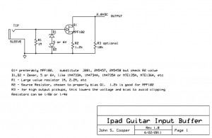
In this video, I talk about how JFET’s work, then work up a circuit diagram (as shown at right).
Then, I prototype the circuit on the breadboard of my Radioshack Electronics Learning Lab Model 28-280, and finally play through the circuit to show how it sounds.More
Building an iDevice Guitar Interface Cable

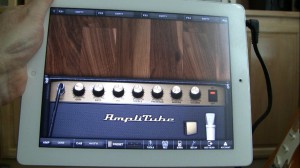
With the availability of apps like Amplitube, AmpKit, and Garage Band, it’s immediately obvious how this device can be an amazing guitar learning and practicing tool. I’ll talk more about that in another article. But before you can plug in your guitar, you need a special interface…
Before we talk about building our own device, let’s consider the alternative. There are a number of commercial interface products available. The less expensive ones plug in through the headphone/microphone jack like IK Multimedia Amplitube iRig, Peavey AmpKit Link, Griffin GuitarConnect. That’s the type of device we’ll be building. Then there are also the higher quality, more expensive products that have their own A/D converters and plug in using the dock connector- like Apogee Jam, Sonoma GuitarJack, Alesis iO Dock, Line 6 Mobile In and IK Multimedia iRig HD.
In part 1 of this 3-part video series, I introduce the project- how to make your own impedance matching, buffered guitar interface for the Apple iPad, iPod touch and iPhone. These iDevices all share a similar headphone/microphone jack specification, so this circuit should work with all of them.

